
Network Architecture
Each DR cluster (primary and secondary) has its own VNet with the following architecture:
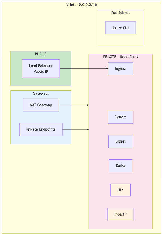 |
Note
UI and Ingest node pools (marked with *) are only created when dr !=
"standby". Standby clusters use digest nodes for all workloads
during failover.
Subnet configuration
| Subnet | CIDR | Type | Purpose |
|---|---|---|---|
| ${prefix}-s-aks | 172.16.0.0/24 | Private | AKS system node pool |
| ${prefix}-s-lsdigest | 172.16.3.0/24 | Private | LogScale digest nodes |
| ${prefix}-s-kafka | 172.16.2.0/24 | Private | Kafka broker nodes |
| ${prefix}-s-ingress | 172.16.4.0/24 | Private | Ingress controller nodes |
| ${prefix}-s-ui | 172.16.6.0/24 | Private |
LogScale UI nodes (not created when
dr="standby")
|
| ${prefix}-s-ingest | 172.16.5.0/24 | Private |
LogScale ingest nodes (not created when
dr="standby")
|
Note
Pod IPs use Azure CNI Overlay (network_plugin_mode =
"overlay") and do not require a dedicated subnet.
Node Pool Creation by DR Mode
| Node Pool | dr="active" or dr="" | dr="standby" |
|---|---|---|
| System | Created | Created |
| Digest | Created | Created |
| Kafka | Created | Created |
| Ingress | Created | Created |
| UI | Created (if cluster type supports) | Not created |
| Ingest | Created (if advanced cluster type) | Not created |
Note
Standby clusters don't need UI or Ingest capacity until failover. Node
pools are created during promotion (dr="standby" →
dr="active").
Node Pool Creation Logic (Terraform):
# UI node pool (logscale-ui-node-pool.tf)
count = var.dr != "standby" && contains(["dedicated-ui", "advanced"], var.logscale_cluster_type) ? 1 : 0
# Ingest node pool (logscale-ingest-node-pool.tf)
count = var.dr != "standby" && contains(["advanced"], var.logscale_cluster_type) ? 1 : 0
Why UI and Ingest Are Not Created on Standby:
Cost optimization: Azure VM costs are eliminated for UI and Ingest node pools until failover
Minimal footprint: Single digest pod handles all functions during initial failover
Automatic scale-up: Node pools are created during promotion via terraform apply, not maintained idle
Resource efficiency: No idle VMs consuming compute resources or incurring costs
Consistent with OCI: Matches the DR implementation pattern used in the OCI LogScale deployment
Node Pool Creation During Promotion: When promoting
(dr="standby" → dr="active"), Terraform
automatically creates UI and Ingest node pools, associated NSGs, and
subnet associations. Expected time: 5-10 minutes per pool.
Network Security Groups (NSGs)
NSGs control traffic flow between the internet, load balancer, and AKS nodes.
1. AKS Cluster NSG (${cluster_name}-aks-nsg)
Inbound rules:
| Priority | Source | Port(s) | Protocol | Description |
|---|---|---|---|---|
| 100 | AzureLoadBalancer | 443, 80 | TCP | Health probes from Azure LB |
| 110 | VNet | * | * | Internal VNet communication |
| 120 | ip_ranges_allowed_to_kubeapi | 443 | TCP | kubectl access from allowed IPs |
Outbound rules:
| Priority | Destination | Port(s) | Protocol | Description |
|---|---|---|---|---|
| 100 | Internet | 443 | TCP | HTTPS to Azure services, container registries |
| 110 | Storage | 443 | TCP | Azure Blob Storage access |
| 120 | AzureActiveDirectory | 443 | TCP | Azure AD authentication |
2. Azure Load Balancer
The ingress-nginx service creates an Azure Standard Load Balancer with:
Public IP address (assigned by Azure)
Health probes on ports 80/443
Backend pool targeting ingress node pool
Azure Storage Firewall
Azure Storage accounts use firewall rules to control access:
| Access Method | Same Region | Cross-Region | Used for DR |
|---|---|---|---|
| VNet Service Endpoints | Works | Not supported | No |
| IP-Based Rules (ipRules) | Works | Works | Yes |
| Private Endpoints | Works | Works (with peering) | Optional |
Key limitation: Azure VNet service
endpoints for storage only work within the same region. For cross-region
DR, the secondary cluster's NAT Gateway IP must be added to the primary
storage account's ipRules.
Storage Firewall Configuration:
{
  "networkRuleSet": {
  "defaultAction": "Deny",
  "ipRules": [
    { "value": "<admin-ip>", "action": "Allow" },
    { "value": "<secondary-aks-outbound-ip>", "action": "Allow" }
   ],
  "virtualNetworkRules": [
    { "virtualNetworkResourceId": ".../subnets/<primary>-s-lsdigest" },
    { "virtualNetworkResourceId": ".../subnets/<primary>-s-ingest" },
    { "virtualNetworkResourceId": ".../subnets/<primary>-s-ui" },
    { "virtualNetworkResourceId": ".../subnets/<secondary>-s-lsdigest" },
    { "virtualNetworkResourceId": ".../subnets/<secondary>-s-ingest" }
   ]
  }
}
Request Flow (Internet → LogScale)
The request flow is shown in the following diagram:
 |
Traffic Flow Steps:
| Step | Component | Description |
|---|---|---|
| 1 | DNS/Traffic Manager | Client queries DNS, Traffic Manager returns healthy cluster IP |
| 2 | Load Balancer | Azure LB routes to NodePort (30000-32767) |
| 3 | nginx-ingress | TLS termination, routes by Host header |
| 4 | LogScale Pod | Processes request, accesses Blob Storage |